C:\ANCIENT\SKETCHPA.TXT
1963
Sketchpad: Tell the Drawing What Must Stay True
Sketchpad let geometry carry relationships: constraints described what must hold, while instances connected repeated shapes to shared definitions.
A line looks horizontal until you move one endpoint. If the drawing stores only two coordinates, it has no particular reason to remain horizontal afterward.
A person knows the intended relationship. The software needs that relationship recorded somewhere if it is expected to help preserve it.
Sketchpad made this an unusually interesting problem. A drawing could contain rules and connections alongside the geometry visible on the screen. Changing the picture could then become a computation over those relationships.
This is a more demanding promise than putting a pleasant line on a display. It asks the program to keep track of what the line means to the rest of the drawing.
A thesis with a working system
Ivan Sutherland’s January 1963 MIT thesis describes Sketchpad on the TX-2. Users indicated geometry with a light pen and controls, applied constraints and reused symbol definitions through instances. The acknowledgments credit advice and support from several people, including supervisor Claude Shannon.1
The linked edition is a faithful 2003 retypesetting with a new preface. The later publication date doesn’t move the original thesis into the twenty-first century, and the preface’s retrospective vocabulary shouldn’t silently become the original implementation’s terminology.
Our examples below are newly invented geometry. They illustrate the distinction between a relationship and its current coordinates without claiming to reproduce TX-2 arithmetic or the historical constraint solver.
Horizontal isn’t a pair of frozen numbers
Choose two points, A at (1, 2) and B at (5, 6). Their x coordinates differ by four and their y coordinates also differ by four. The line slopes upward.
The rule “horizontal” requires the two y coordinates to be equal. It doesn’t, on its own, say which point should move or what their common height should become.
If both points are free, there are infinitely many satisfying outcomes. Both can finish at height two, four, six or any other shared height. Their x coordinates can stay as they are because this particular rule doesn’t constrain x.
For an original model, choose the outcome that minimizes the sum of squared vertical movements. If their common final height is h, the cost is:
(h - 2) squared + (h - 6) squaredAt height two, the cost is zero plus sixteen. At height six, it is sixteen plus zero. At height four, it is four plus four: eight.
Rearranging the expression gives twice (h - 4) squared plus eight. The smallest cost therefore occurs at four. A moves up two; B moves down two.
The horizontal condition is satisfied, and the additional movement policy chooses a particular answer from the many possible ones.
Pinning changes the answer
Now pin A at height two. The horizontal condition requires B to join it there. A stays at (1, 2) and B becomes (5, 2).
The total squared movement is sixteen. That is larger than eight, but the free-points optimum is no longer permitted: moving A would violate its pin.
Pin B at height six as well, while retaining both pins and the horizontal rule. The requirements become inconsistent. A must have height two, B must have height six, and they must have the same height.
No clever sequence of small movements can produce an exact solution to those three statements together. The program needs a way to recognize or report the conflict, or a clearly stated policy for accepting residual error.
Our checker rejects this contradictory exact case. That is our chosen teaching policy, not a claim about the message the original Sketchpad would have displayed.
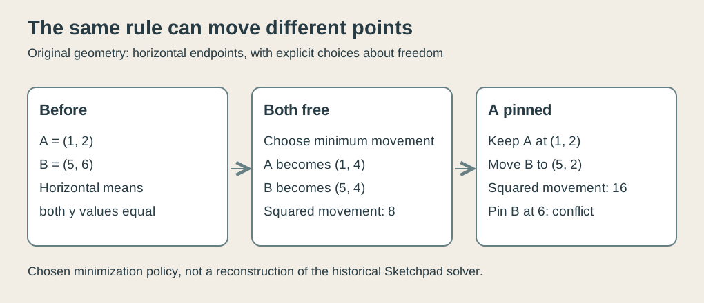 Original explanatory SVG, created in 2026. Invented endpoints and a minimum squared movement policy; no recovered Sketchpad solver or screen.
There is a practical distinction here between “the solver failed” and “the requirements admit no answer.” A drawing interface should help a user understand which problem they have before encouraging another round of dragging.
Check the residual separately
A residual measures how far a condition remains from satisfaction. For our horizontal rule, use A’s y coordinate minus B’s y coordinate.
Initially the residual is minus four. At the shared height four it is zero. At the pinned-A solution, it is also zero.
Those two solutions satisfy the same rule despite having different coordinates and movement costs. The residual and the movement objective answer different questions.
A tempting mistake is to verify only that something moved. A sequence can change both endpoints repeatedly while leaving the horizontal residual nonzero. Another is to minimize movement by doing nothing, obtaining a wonderfully cheap drawing that still violates the requirement.
The checker verifies the final relationship and the chosen cost separately. It also leaves both x coordinates untouched. A vertical adjustment shouldn’t quietly relocate the drawing sideways.
The thesis discusses both one-pass satisfaction and a relaxation fallback, with limitations for complex cases.1 Our direct two-point calculation is much smaller. It doesn’t turn the historical system into a modern universal optimizer.
Connections need an identity
Suppose two segments meet at point B. One runs from A to B and the other from B to C. If both segments refer to the same stored point, moving B changes both connections together.
If each segment instead holds its own unrelated copy of B’s coordinates, equal values merely make them coincide for now. Changing one copy can open a gap.
Our original miniature model stores points under names and represents a segment by its endpoint names. Move the one B record, then derive both segments’ coordinates from those references. Both now use the same updated endpoint.
This is a choice about structure. Drawing the segments in the same color or displaying them at the same location doesn’t establish the shared identity in the data.
The thesis’s explicit topology and ring storage support relationship handling.1 Our named-point dictionary is a teaching substitute, not a transcription of that ring structure.
A definition and its placements
Repeated shapes bring a related distinction. A drawing can contain two independent copies, or two placements that refer to one shared master definition.
Choose a master with local points (0, 0), (2, 0) and (2, 1). Place instance A by doubling its coordinates and translating by (10, 0). Its displayed points are (10, 0), (14, 0) and (14, 2).
Place instance B using a quarter turn counterclockwise, without scaling, followed by translation (0, 10). Its points become (0, 10), (0, 12) and (-1, 12).
Both placements refer to the same three-point definition. Their separate transformations explain why the displayed coordinates differ.
Now edit the master’s last point from (2, 1) to (2, 2). Instance A’s last displayed point changes from (14, 2) to (14, 4). Instance B’s changes from (-1, 12) to (-2, 12).
The edit travels through each transformation. Neither placement needs its own manual correction.
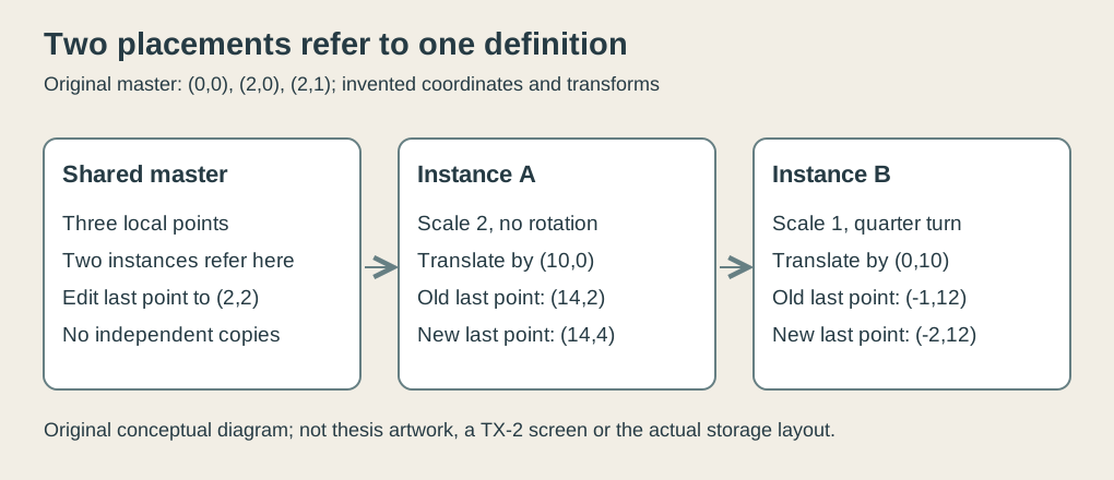 Original explanatory SVG, created in 2026. Chosen point list and transformations illustrate shared definitions; no historical drawing or storage layout reproduced.
Change only instance A’s translation instead and instance B stays where it was. Shared shape and local placement are separate responsibilities, which is why both kinds of edit can behave sensibly.
The representation has a period boundary
The original thesis represents an instance using center coordinates and size multiplied by sine and cosine of rotation. It explicitly notes the absence of mirror-image instances.1
Our example describes scale and angle separately because a quarter turn is easy to inspect. That explanatory choice isn’t an assertion that the original stored four independent fields for x, y, scale and angle.
A reflection also deserves its own boundary. Turning a right-handed shape around doesn’t necessarily produce its left-handed counterpart. Rotation preserves orientation; reflection reverses it.
For our three points, the signed cross-product of the two edges from the first point is positive two. After a quarter turn it remains positive two. Reflecting x instead would make it negative two.
The checker verifies that distinction with exact integers. It explains why a missing mirror operation can’t be supplied merely by finding a sufficiently dramatic rotation setting.
Reuse can introduce a loop
A definition can, conceptually, contain a placement of another definition. Expanding it for display then means following the references and applying their transformations.
In an original small graph, master Frame contains two placements of Corner. Expanding Frame visits Frame and then Corner twice. Reuse doesn’t require duplicating Corner’s stored definition.
Now imagine adding a reference from Corner back to Frame. Naive expansion enters Frame, then Corner, then Frame again, with no reason to finish.
Our checker detects a definition already on the current expansion path and rejects that cycle. It allows Corner to appear twice on separate completed branches: repeated use and recursive self-containment are different conditions.
This is a conceptual safety check, not an implementation claim about the original display routine. It makes the cost of preserving useful relationships visible: the software also needs rules for following them safely.
The drawing carries an agreement
I find the horizontal example the clearest expression of the idea. Two y coordinates can happen to match, or the drawing can carry an agreement that they should continue to match.
That agreement still leaves choices about freedom, pins, movement cost and inconsistent demands. Likewise, a repeated shape can carry a shared definition while retaining its own placement.
Sketchpad made relationships part of what a drawing program could work with. The result wasn’t just a cleaner way to draw a line. It gave the computer enough structure to help keep the intended drawing together.
Footnotes
-
Ivan E. Sutherland, Sketchpad: A Man-Machine Graphical Communication System, January 1963 thesis, faithful 2003 electronic edition. Abstract, acknowledgments, instance representation and constraint-satisfaction sections inspected. All coordinates, minimum-movement choices, dictionary model and checker policies here are original teaching examples. ↩ ↩2 ↩3 ↩4