C:\1980S\AUTOCAD.TXT
1982
AutoCAD: Drawing Becomes Programmable
How early AutoCAD turned desktop drafting into editable geometry, reusable parts, and a practical business on small computers.
A repeated detail is a small nuisance on a drawing and a large nuisance when it changes. If a plan contains twenty copies of a part, the interesting design decision may take a minute. Getting twenty representations to agree can take rather longer.
Early AutoCAD helped turn that maintenance work into operations on geometry. A line retained endpoints. A circle retained a center and a radius. A reusable part could retain its definition while different placements supplied their own position and orientation. The drawing became something a program could manipulate without asking a drafter to reconstruct every mark.
Its other achievement was making this work practical on microcomputers. Autodesk’s release record dates AutoCAD-80 to December 1982 and AutoCAD-86 to January 1983.1 The slightly untidy chronology is useful: the familiar IBM PC product was one branch of a development effort spanning several machines.
A company looking for a useful place to stand
AutoCAD grew from Michael Riddle’s Interact and the programmers around Marinchip Systems. John Walker’s September 1981 strategy paper already discussed moving Interact and other software to a different processor. It also recognized a commercial weakness: tying the future of useful software to hardware whose market prospects were deteriorating.2
That context makes Autodesk’s founding in 1982 less mysterious. The company wasn’t formed by a group that already knew CAD would become its enduring identity. It was an effort to turn a collection of programming skills and prospective products into a workable business.
Walker worked on the CP/M-80 implementation. Dan Drake and Greg Lutz worked on the 8086 branch, targeting the Victor 9000 and IBM PC respectively. The platforms demanded different display work, and the CP/M version initially took the lead in feature development.3 The engineering was portable in intention and obstinately particular in execution. Computers have a habit of becoming individuals when you ask them to draw.
The COMDEX demonstration in November 1982 helped establish where the demand lay. Drake’s preserved meeting summary describes AutoCAD running on Z80, Victor, and IBM machines, with interest substantial enough to raise immediate questions about who would handle the sales leads. By the January 8 meeting, the group reported four AutoCAD-80 sales and one AutoCAD-86 sale; the 86 release was scheduled for January 15.4
Those small numbers are worth keeping. A successful demonstration and an established business are different things. The founders still had to decide how to pay people, maintain the product, and turn attention into orders. At that point, a $1,000 monthly payment allowed Lutz to continue full-time work. The drawing software was gaining customers while the company was still arranging how to remain a company.
Geometry keeps its identity
The core distinction in this article is between storing a picture and storing descriptions of its contents. A picture can tell us which pixels are dark. A geometric model can tell us that an object is a circle and where its center lies.
For an original teaching example, suppose a simple mechanical plate contains a circular hole of radius 5 drawing units at (20, 30). The circle’s equation is:
The file needn’t store every possible point on the circumference. A compact description supplies enough information for software to generate a display or plot. Moving the center to (50, 30) changes the hole’s placement while preserving its radius.
That representation makes editing meaningful. A program can move the circle, copy it, or place it on a different layer without pretending that the circle is a collection of unrelated marks. The drafter can inspect a detail at a different magnification while its stored dimensions remain the same.
The distinction also prevents a common misunderstanding about accuracy. A coarse display can show only a rough visual approximation of a small feature while the stored geometry retains more precise coordinates. Zooming changes the view. It doesn’t improve the underlying design merely by making it look larger.
The early system worked with entities, layers, and an explicit regeneration process. Walker’s log documents screen navigation, insertion, and drawing interchange as active engineering concerns.3 None of that warrants attaching today’s parametric modeling, modern object snaps, or a building-information model to the first release. A useful early drafting tool deserves to be understood on its own terms.
Reuse without drawing the part twenty times
One of the most interesting entries in Walker’s log describes a redesigned insertion mechanism: a block definition held the part’s entities, while a block reference supplied position, scale, and rotation. The definition was copied into the drawing, keeping the drawing self-contained.3
Here is what that arrangement means mathematically. Take a tiny L-shaped part with points:
| Point | Local coordinates |
|---|---|
| A | (0, 0) |
| B | (4, 0) |
| C | (4, 3) |
A placement translated by (20, 30) produces A at (20, 30), B at (24, 30), and C at (24, 33). The stored part can retain its local coordinates; the reference describes the transformation.
For uniform scale , rotation , and translation , an explanatory two-dimensional transformation is:
This is a teaching formula, not a reconstruction of AutoCAD’s source routine. At unit scale and a 90-degree counterclockwise rotation, point B becomes (0, 4) before translation, then (20, 34) afterward. Point C becomes (-3, 4), then (17, 34).
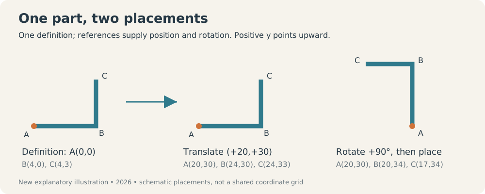
New schematic teaching illustration, created in 2026; not an AutoCAD screenshot and not drawn to the example’s coordinate scale. Different references place a shared definition.
The practical advantage extends beyond saving keystrokes. A part has an identity the software can carry through operations. You can discuss its position separately from its geometry. That is an unusually productive separation when a drawing contains many instances of the same detail.
It also creates a decision about dependencies. Should the drawing contain its parts, or should it fetch them from outside files? The former makes a file easier to carry intact. The latter could simplify sharing updated definitions but introduces things that can go missing. A reusable model has acquired a small information-management problem along with its geometric convenience.
A scale belongs to the output
Consider another invented example: a room 12 feet wide, drawn using inches as the coordinate unit. Its model width is 144 units. For a sheet printed at one-quarter inch per foot, the paper-to-model scale is:
The printed room width is therefore inches. At one-eighth inch per foot, it becomes 1.5 inches. The room has not shrunk; the representation has.
This arithmetic illustrates the separation between geometry and output. It is not a claim that the original release offered modern paper-space layouts, viewports, or an automatic command that performs every step. The earliest system’s drafting and plotting capabilities must be kept distinct from later workflow conveniences.
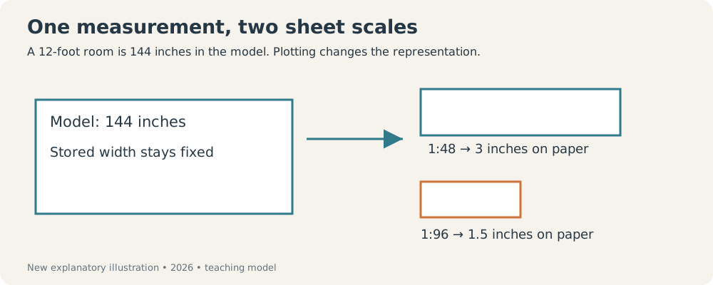
New explanatory diagram, created in 2026. The scale arithmetic is an invented teaching example, not recovered AutoCAD output.
The conceptual benefit is that a drawing can be checked and revised in its own units before choosing a size for presentation. A user still has to choose the units consistently, select a sensible plot scale, and ensure the sheet’s annotations communicate that choice. Software can preserve a measurement perfectly while a person interprets it in the wrong unit. Precision and agreement are separate achievements.
The memory budget had opinions
AutoCAD-80 had to run on a machine with 64 KB of memory, only 52 KB of which was available to user programs. Walker’s log describes splitting overlays as features pressed against that budget.3 An overlay let part of the program occupy memory when needed instead of requiring all its routines to remain resident together.
This constraint helps explain why a modest feature list could still require sophisticated engineering. Geometry, interaction, file management, and device support had to cooperate in a space a modern photograph would consume several times over. The limitation belonged specifically to the CP/M branch; it should not become a claim that every early AutoCAD platform had the same available memory.
Release chronology matters for features too. Autodesk’s retrospective table dates scripts and hatching to version 1.4 in October 1983, polylines to version 2.1 in May 1985, and associative dimensioning to version 2.6 in April 1987.1 The familiar command vocabulary accumulated over time. Reading it backward would make the launch product look uncannily well prepared for its own future.
Early dimensioning is a useful case. Development notes mention a simple implementation in December 1982, while January meeting notes discuss an independent $500 add-on and the release table dates dimensioning to version 1.2 in April 1983.41 Those records describe different stages. They don’t justify claiming that every December customer received the later dimensioning system in the base package.
The drawing has to leave the desk
A professional drawing is rarely useful only to its author. It may be reviewed, plotted, copied, or processed by another program. Autodesk’s release history identifies DXF drawing interchange with the initial release.1 The importance is straightforward: geometry needed a route between tools and machines, beyond whatever internal representation each implementation happened to prefer.
Interchange is less glamorous than drawing a complicated shape, but it answers a more durable question: can someone else use the result? A file can be compact, precise, and entirely inconvenient if the next participant cannot read it.
AutoCAD’s early achievement brought these concerns together at desktop scale. It made edits act on stored geometry, gave repeated parts reusable descriptions, and treated delivery as part of the work. The company still had to sell and support the result. The drafter still had to design something sensible.
The significant change was that maintaining the marks could increasingly become a software operation. That left more room for the professional judgment the marks were supposed to communicate—and plenty of opportunity for another revision.
Sources
Footnotes
-
Autodesk/John Walker, “Product Release History”, The Autodesk File. Retrospective platform shipment and feature tables. Used to separate prototype work from documented product releases. ↩ ↩2 ↩3 ↩4
-
John Walker, “Before Autodesk,” September 29, 1981 strategy paper, preserved in The Autodesk File. Primary document on Interact, software conversion, and Marinchip’s commercial context. ↩
-
John Walker, AutoCAD-80 Development Log, July 1982 onward. Primary notes; proposals and installed features are distinguished, and statements about the CP/M version aren’t automatically applied to the IBM build. ↩ ↩2 ↩3 ↩4
-
Dan Drake, “Meetings: December ‘82, January ‘83”. Participant’s summary documenting COMDEX, early sales, planned release, staff pay, and the dimensioning add-on. ↩ ↩2